Question : What are the differences between stock and "racing" motors?
Is a Mabuchi "F" can a "racing" motor? It has been discovered that this is the motor in the Scalextric cars that we have. I want to say E-17 but I have conflicting data so that model number is a bit elusive to me. And also, if it is NOT a racing motor, can it be exchanged for a "real" racing motor like a Cheetah ? I printed the motor list from a while ago, but it doesn't clarify just what qualifies as a "racing" motor. To try and be clear (for those who think I'm confused), a while back we dabbled in HO. It was found that the Chassis is a key component. Life-Like chassis could not be altered as well as a Tyco 440 X2 or an AFX G-Plus chassis for example. Then, as time went by, we found out even MORE stuff. Different armatures, Neodymium magnets, motor magnets, traction magnets, more amps from the transformer to move the cars now with "silicone" tires ... AUGHH !! It was becoming too much ! And above all else, there were the "collectors" who would try and bargain with you for a different car like the Pancake motor chassis from the "Model Motoring" days. Well, to make a long story short, it was thought better if we went to something more "simpler" as in 1/32nd scale. More people were involved. The cars were not called "pocket rockets". The detail was immaculate. And, above all else, you could see them better as they sped along the track. Back to speed, can the motor be upgraded like the HO cars or is Scalextric a "one-motor" car ?
If you consider the engine in your lawnmower a racing motor, then yes. If not, then no. The "F" can is the lowest common denominator for a slot car motor since the Eldon motor of the 1960's. A "Cheetah" is not a "real" racing motor either, but is definitely better. However, you cannot get one anymore because they have pretty much sold out and Mabuchi is not willing to make new ones with the vent holes. So get a "Falcon" that is exactly the same, and probably better. [Mr. P]
There are many factors that make one motor better than another. You asked about motor windings and wire gauge that make a difference and what are they. It comes down to the size diameter of the wire and the amount of wire on a pole. The wire diameter determines how much current can flow through the wire. The larger the diameter the more electrons that can pass through the wire. The length of the wire or the number of turns wrapped around the pole also determines how much resistance for how long the electrons find to passing through that length of wire. The shorter the length of wire the less resistance to flow. So the first example we will use is 35 AWG gauge wire. That size is determined by a set standard of the electrical industry. American Wire Gauge (I think) it's been a while. #35AWG is smaller in diameter than say #23AWG wire the smaller the diameter the less electron flow or current draw (amperage). Now wire length determines for how long that amount of electrons is impeded from flowing through that length of wire. 100 turns impedes flow more than 20 turns. It is a longer length of wire to traverse. So a motor wound with #35AWG wire with 100 turns will be a much slower motor than one with #23AWG wire with only 20 turns. The 23 AWG wound motor will be a lot faster motor. Now that said, there are consequences to this. The #35 wire will be a cooler motor to run, with low rpms and would be found in maybe some of the Euro slot cars coming in. The #23 wire motor would be a real handful and be found in "a Grp 7" motor and would produce a lot of heat and rpm. It would draw a very heavy current flow especially on start up. That is a result of a large diameter wire for a short length of travel. Now this all just the basics, many other factors come into play with the slot car motor. Things such as the length, diameter and material the armature stack is made from. Also to consider is the can type, size, thickness of material, motor magnets, size magnets, material used. Then location in the can, distance of the magnet from the surface of the arm etc. Also to be considered is the amount of power available to feed the motor it an electron supply. The #35 wire motor can run on much less power that that #23 wire motor. Hope this helps a bit. It is a very rough and quick breakdown of what happens in your slot motor. It becomes somewhat of a real science as you progress from class car to class car as to the performance you want or need. I am sure others can add to this or correct me if needed. Have at it.
Well, you didn't say WHICH Mabuchi you considered standard, so I will try to wander into things.
1) Mabuchi "FC" cans, like the Ninco NC1 are 13mm high, with an extra 2mm for the brushes and lead wires. The "FK" cans, like the Plafit Fox, with the leads coming out the END of the motor are 14mm high, but can often give more room because of the brush mounting. Internally, everything is the same, so nothing prevents you from putting the arm you want into the can you want. My Coopers have room for these motors, so I am not sure what happened. Well, unless you are using a frame that is UNDER the motor. Not sure.
2) Old 13uos like the Johnson 111 that used to be in the Scalextric cars, and the X88 that used to be in the Monogram F-1s are 13mm high with end mount leads. Again.....
3) It just occured to me that you might be referring to using a 16d or something .... which are currently 17 mm high. See above.
4) Modern motor availability ... Dunno. You might consider a Hot HO motor like some of the BSRT replacement motors for the Tyco 440. [Fate]
Actually, if you will compare the arms from, say, a Ninco and a Fox, you will find that, despite the different brush layout, the arms are constructed and timed exactly the same. The slot on the com is in the center of the stack. If you think about it, it makes sense that they make different cans for different mounts and applications but only one ARM. Most of the time, the differences between arms is the wind, often one being a de-wind of the other. So, it IS and option to get a little room by using the FK can ala Fox, Falcon,Cheetah, lil Ripper, and a milder wind out of, say, a NC1, Rabbit or Evo or Scalextric. Fly is a good choice usually having the better molded com. [Fate]
Fate : Did you measure the resistance of the windings? I have found that the Evo's seem to have about one ohm less resistance ! This may be due to better contact on the commutator lugs on the two I measured. The Evo's that I have see certainly seem to perform marginally better but they are all way behind the Rabbit that costs half as much. What we need is a disabled Rabbit that we can all use for a "Vintage" Class racing. The Sakatsu 200 is probably the best for this class of car. [Phil Kalbfell]
Phil : If you want a disabled a Rabbit or any other low amp motor for that matter just put a resistor in series with the motor. Choose the resistor ohms based on how much you want to "disable it". Around 1ohm is a good start. Take your operating voltage x the motors current draw x 1.4 and that will give you a good safe watt rating that will stay cold. You can go to under x 1.4 to x1 if you don't need to be mil spec (for Rocky). [Jim]
Ya'll know one of my pet hobby horses is the funning specs I see published about the motors we buy. "FICTION" I keep yelling, then people go on like nothing was said arguing if X is better than Y because it has more RPM printed on the label. Well, it happened to me again. Scott wants me to build a Soveren 32 GT car. And I have been casting around buying parts. Sigh. He indicated that either the NC1 or Pro-Slot evo1 were legal motors for the class. Confused me, truth in advertising time. The Evo says 18,000 RPM at 12 volts The NC-1 says 14,000 RPM at 13.5. If these numbers had meaning, the Evo ought to be a lot faster. Well, near as I can tell from taking both apart is that the only difference between the motors is the LABEL Otherwise, they are mechanically the same, same wire, wind, stack, endbell, can and magnets. Just different labels. [Fate]
The best inline bracket for slot cars whether 1/32nd or 1/24th is the Inslot bracket made by Inslot. They make them for both the the stupid heavy 16d motor as well as the nicely balanced Pla-Fit or the new Falcon motor. There is a difference between the brackets, so make sure you specify which you want for best fit. I have used the brackets several; times with great success. They are strong like a bull and can be driven over by a truck and not be damaged.
For sidewinder brackets I either make my own, or use the rear sections of the Parma I-32 chassis or the rear of the Pro Slot Demon chassis or the mounts, after cutting them off the original chassis. Works well for me when in a hurry. The arm must have the correct timing for the can the brushes are in different locations in the cans with the end bell fitting inside the can ie NC2 Fox etc ! [Larry S.]
Actually, if you will compare the arms from, say, a Ninco and a Fox, you will find that, despite the different brush layout, the arms are constructed and timed exactly the same. The slot on the com is in the center of the stack. If you think about it, it makes sense that they make different cans for different mounts and applications but only one ARM. Most of the time, the differences between arms is the wind, often one being a de-wind of the other. So, it IS and option to get a little room by using the "FK" can ala Fox, Falcon, Cheetah, lil' Ripper, and a milder wind out of, say, a NC1, Rabbit or EVo or Scalextric. Fly is a good choice usually having the better molded com. [Fate]
Hi, I am currently working on a beautiful Cooper Climax from Dave Cooper : and I find that standard Mabuchi type cans are a tad low, indeed sticking out from below the body by more than 5mm. What options are available ? Alternatively what else will fit under there ? Cheers ... [John McLennan]
John : I have several of these F1 bodies and most of them are very difficult to get the motor right up under the body. The Cooper and Eagle being the most difficult. One chassis I built I used spring wire each side of the motor and allowed the motor to hand below the chassis and body (like a Scalextric). I think it looks bad like this. The other two cars I am still building will be using HO style motors, One from a Polistil car and one from a Pink Kar. The Ninco Go Kart motor is similar. These both will probably need to be rewound to get some more performance. I also have a car running using a Mabuchi motor from a CD player ! This motor is 15.5 x 12 x 27 mm but has not got carbon brushes, but they seem to be lasting OK so far. This would be by far the best choice if I could find a local supply for these here in Australia. The biggest problem with these and the HO motors is the shafts are only i.5 mm dia so the pinions have to be bushed with a piece of brass tube and drilled to 1.5mm. If you come up with any other answers please let me know as I still have several more cars to build. [Phil]
I would offer a couple options to you on this. Just as the Evo 1 and NC1 are the same motors, and the Rabbit, Carrera motors are identical, so, the MRRC, Scalextric, and Fly motors are identical. Well, sort of. The Fly has a much better commutator, and that should translate into a longer life ! Without taking them apart, you can do a whole stack ohm measure and compare (I dont want to go into parallel resistor stuff right now, I think most people don't want to disconnect the stack for an "accurate" measurement then try to solder again to that cheap com), whole stack, the Rabbit measures 3 ohm, the Fly 5. Which would qualify, I think, as a "slow" rabbit. It is easy to reverse the shaft on the fly motor to be can drive (Soveregn 1/32 does this all the time with NC1s). OH, go to the electronics store looking for the small black diodes with a silver band that Professor Motor controller uses. These are only rated to 3 amps, but if you have a car pulling more than 3 amps .... Anyway, these things are a buck apiece. Just put, oh, 3 on each lead between the motor and the car. This drops the voltage to the motor by .7volts per diode. Without limiting amperage draw. Cheap, easy and removable. On this last, Well, I cheated ! The locals who freak out that I can cheat without being caught, have a strange rule that all 12 classes must use NC1s. They put NC1s into Fly Cars and everything. One of their group still talks to me and has an electronics background (ok he is an engineer for a security company). I reminded him of what he knew, and he found that he could put 4 diodes in the circuit, 2 on each lead) and the car performed as if it was a Ninco (well, a little better, but they TRUST him). No one has looked at this point ! If you wanted, you could put a slide switch on the outside like a Carreara car, to switch in the diodes so that the car would still perform for the experienced racers, but be down-rated for the novices. [Fate]
3 amps is probably overkill - a 1 amp diode will hold the current for anything like a Scalextric or Fly motor - should be able to buy a bag of ten for $1
Hi ... I would have agreed with you once. But in recent times I have had all sorts of people report all kinds of high amp draws to me that seem amazing. I don't think anything I built would need more than 1 ampere, but some people tell me they cannot run a fly car on 3 amps ! ARRGH !
The second reason for mentioning the 3 amperes is that everyone with a Slot Works or Professor Motor controller has SEEN the diode and would recognize it by sight. The others ... [Fate]
Question : What is meant by the term "timing" of the armature of a slot racing motor?
Here is a rough drawing of a simple arm (armature) timing setup with only the Arm showing the stack and the commutator relationship to each other. It shows the arm from the commutator end and the timing is set for the arm to rotate CCW (counter clock wise) viewed from this end. The motor in question though will be rotating actually in CW direction when viewed from the can end of the motor or arm. Just wanted to show Tropi how the timing of the stack and comm related where it starts from and where it goes to. With just a 10 degree advance positively. The other direction would of course be the negative time version. Yeah I know it all sounds like mud. This is not the timing found on Cheetah/Fox/Falcon motors though. That is a whole other style of timing and direction. Next on the list of things to do.

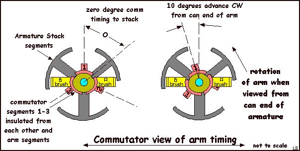
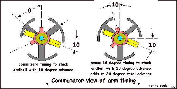
These drawings were in response to a question about timing of the comm. The first picture is just one way of timing the comm to the arm stack. It is very basic. The arm timing determines the advance the arm sees and basically determines which way the arm will turn to the best advantage in the motor. Which affects RPM, torque and brakes of the particular motor. I did not show the brush relationship in this drawing to keep it simple. The brushes would be shown in this picture to be in the center of the arm, horizontally on each side. or at 90 degrees to a vertical line through the center of the arm. Now by rotating the brushes equally in one direction or the other, that will also advance or retard the arm timing. The next two pictures depict other ways of timing and arm. Like a twister style motor uses that form of timing adjustment to either advance or retard the arm which will usually have the timing advanced on it by the comm position. Say the motor comes with a arm timed at 45 degrees and you find you don't have enough brakes or it has too much top end for your tracks straight length. So with the twister motor you can use the adjustable endbell to retard the 45 degrees back to about 38 degrees which will change the brakes, torque, and RPM. Or say you find you are a little short on RPM, you can advance the endbell to say 52 degrees. You would gain RPM, lose some torque and brakes. This still does not explain the Cheetah/Fox/Falcon style of timing completely that will take another drawing and description of what they are doing with what I believe is a star type wind with timing built into the end bell.
The pinion and gear direction/location are basically determined by the motor timing you are using. If the motor is really and truly at zero advance in timing the gearing could be on either one side of the pinion or the other and not make much difference. But if the motor has any built in advance timing there will be one side the gear should be on to take advantage of the better RPM. This will usually be apparent when setting up the motor on a power pack, at the bench if not certain when you buy it.
Also when using the home set car motors they will be determined by which end of the motor the manufacturer has installed the motor in the chassis. Hopefully they know what kind of timing their motor has or not. I think most of the motors used are supposed to be very close to zero degree timing but as the quality control is so bad the motor could be timed 10-15 degrees in either direction. Which determines in many cases why the identical type motors will have a few very fast ones and a few that are not as fast. Some got a bit more advance timing and the others may have gotten a bit of retarded timing when assembled. Which makes getting a good home set motor a bit dicey as far as performance goes. Of course your RPM may vary and ETC. Many other variables are at work in the slot cars performance you get. [Larry Shepard]
Question : What is the history of slot racing motors?
1957: Scalextric introduces commercial slot car sets. The motors are ugly tin cans made in Japan.
1958-1963 : all kinds of model train motors are converted to slot racing use, by Pittman and others. Scalextric introduces the pole motor in their line in 1960. Scalextric used their own open pole motors for a long time, then went to Chinese copies of FT16 motors in about 1967/68, then by 1977, Chinese copies of the "other" Mabuchi, the narrower FT13UO, a motor originally used in the Monogram Midget and 1/32 scale Formula One cars. Now they seem to have adopted the same Mabuchi "S" can as the others...
1964 : A Japanese company by the name of Mabuchi introduces a line of specific slot racing motors, the FT16 surviving as the most popular by 1966.
1967 : American companies MURA, Russkit and Champion, fed up with the intransigent Japanese attitude of Ken Mabuchi, make their own motors using the same overall sizing as the FT16, now commonly called "16D".
1968 : The industry collapses, leaving a wake of bankrupt businesses and millions of dollars of unsold inventory, much of it dumped for tax advantages.
1970 : Surviving micro-companies Mura and Champion down-size their motors and introduce the "C" cans, 1/16" lower and narrower than the FT16 ("16D") copies. These take over the racing scene and are also used in RTR cars produced in small quantities by surviving manufacturers.
1977 : As Mura and Champion cannot produce a low-cost version of their motors, Parma goes to China and has a "16D" sized motor produced for their RTR production.
1988 : Champion is sold and no longer produces motors. It now markets re-badged MURA motors.
1996 : Champion produces RTR cars with Parma motors.
1996 : Mura is sold and stops the production of the "C" can, while producing similarly sized evolutions of this motor.
2001 : Mura ceases all activity and assets are acquired by Koford.
The "D" can is now only made by Parma. What they now call the "C" can is sized 1/16" lower and narrower than the "D", and can use smaller armatures. The "C" can is also a bit large for (but will fit in) many 1/32 scale cars, is way too large to fit in the Marconi Minis, and those come with a HO-sized ST020 motor anyway.
All the smaller motors used in today's 1/32 model racing cars are based on the Mabuchi "F" can, which is a rather cheap one-time use throw-away piece that costs the manufacturers about a buck. The "C" can is much larger and really not as suitable for home-racing use as the Mabuchi "Cheetah" and its clones, sized like the "S" motors, but now no longer available. These have now been upstaged by the recently introduced "Falcon", a clone made in China, and sized like the "S" cans but using can-drive. They can fit in most home racing cars but will need some alterations of the plastic motor mounts. They have nearly twice the power of a "S" series can except for the specialized ones like the Slot.It V12, that can compete almost on equal footing with the Falcons. The Falcon has approximately the same performance as a Parma "Death Star" 16D, but in a much smaller and lighter package. The ST020 was the Mabuchi appellation for the HO sized motor first found in the TycoPro, and then adopted as the standard size for most HO can-type motors up to this day. Marchon is a company making ST020 sized motors, and the armatures and magnets of the Super G-Plus by Tomy fit in one of those cans. [Mr. P]
I ran into a problem today and came up with a solution. The solution is so obvious that I am certain it has been described (and perhaps even commercialized before but - there may be other innocents out there like me so:
I was repairing a car that had chewed up and spit out its gear set (and they were Slot-It gears, not easy to do) I replaced them with a steel pinion and bronze crown gear (64 pitch), shimmed them carefully for clearance and tried a gentle rotation by hand - terrible ! They were rough, stiff and uneven ! I checked the clearance, checked the axle for straightness and the bearing for alignment - all O.K. Maybe a bad gear set - tried another - same result. So I sat and stared - and looked carefully and finally saw that the (soldered in) motor was misaligned - it was square with the chassis and axle but the motor shaft was not in the same plane as the axle - i.e. the motor shaft, extended, would not pass through the center of the axle, bad business. I whipped out my motor soldering iron (150 watt American Beauty truncheon) and made several attempts to correct matters. Critical alignment of a hot motor and a hot chassis with the one hand that is not holding the iron is dicey. After several less than successful attempts, I devised the following : I took a small block of brass - about 3/8" X 3/8" X 1/4" and drilled it through the long dimension with a 3/32 drill and then cross drilled it through the other long dimension 0.78". I then drilled down into the two bores and tapped these holes for 1/72 set screws. Pass an axle blank through one bearing, the block and then the second bearing. Lock with set screw. Insert motor shaft into the 0.78" bore and lock. Swing motor down into place, center it and solder. Voila ! (and the gears worked)
Why such a big iron - doesn't it overheat the parts - no - quite to the contrary, the big iron and its big tip can deliver heat very rapidly so the area of interest is heated to soldering temperature before the rest of the piece gets warm [EM]
Congratulations, Alan. You have just described a Eurosport F1 motor installation block. Eurosport guys have been using similar devices for years. Some are even two piece devices, that are held together (top and bottom) with allen bolts, so that when done, you simple remove the bolts, separate the two pieces, and as you say, Viola ! instant soldered in properly aligned motor. Although, I rarely set my motors centerline in the same plane as the axle, usually lower by up to.080, to get the motor as low in the chassis as possible. It does take some careful running in of the gear set to do this, but it does work. My last years Proxy Porsche was done this way, and ran very smoothly (still does), I think it is closer to.090 out of alignment. Also, gotta agree with you on Hot Irons doing less heat damage, I use an 80 Watter, and crank it up to 130+ volts on my handy dandy Variac.
Return to FAQ Page
|
|
|
